The Studio Scale Star Wars All Terrain-Scout Transport (AT-ST)
Mar 26, 2024
8 min read
0
4
0
Day 1 - 202401.04
Perhaps one of the most menacing Imperial vehicles seen throughout the Star Wars universe, at least to me, was the All Terrain Scout Transport (AT-ST).

It was seen extensively in Star Wars: Return of the Jedi stomping its way through the landscape on the forest moon of Endor. I've always loved these series of vehicles and have always been eager to build one of my own.
However, I didn't want one of the commercially available plastic kits. I was looking for something that, once displayed, would command attention. Short of building a full scale replica, I went in search of something I could 3D print and construct in the studio.
I found 3D artist Cristofer Adrian's offerings at GoldenArmor 3D Models just what I was looking for. First of all, visitors to his website are overwhelmed by the number of items he has posted and one could easily spend an afternoon browsing his creations. Not only does he offer STL's, but there are also resin garage kits and tutorials that out of this galaxy.
I'm basically a canon builder, or as close to canon as my skills allow. Typically, when I set off on a new build, I do a lot of research on the subject matter and try to find as much information as possible. Obviously, trying to match colors and details goes without saying, however, I like my builds to make sense. Meaning, if this imaginary model were to exist in the real world, would any effects shown on a movie screen actually make sense?
A prime example can be seen in the 1979 Star Trek: The Motion Picture departure scene of the U.S.S. Enterprise. It's beautifully docked, and as Capt. Kirk gives the order to depart, a start up sequence of spot lighting and impulse engines comes to life. And it looks amazing on film. However, much of the lighting for the registry markings, in real life, would have no light source. Like, where is that light supposed to be coming from? For me, it has to make sense and I'll always try to work out a solution so my static models make logical sense ... if that makes sense. And now that I've gotten way off point, let's get back to the Star Wars universe.
I know you're all eager to dive into the build, so let's go.
Day 2 - 202403.20
It's been a few months since I first started talking about this build. My real-world job had me traveling, and I wanted to clear a few other projects off the bench before focusing on the AT-ST.
Cristofer's STL files are extensive and contain a great deal of print files, images and PDF information. I decided to create a spreadsheet to manage all of the parts as they came off the printer. I also printed all of the reference photos Cristofer provided and bound all of it in a three-ring binder.
And so, the printing process begins. I'm running two AnyCubic resin machines to help speed up the process. My workhorse machine is the AnyCubic Photon Mono X. I recently added the AnyCubic Photon M3 Max, which has a larger build volume.

The AT-ST main head didn't complete the print cycle and as a result, the lower chin armor didn't form. Total user error with the new printer and not keeping the vat leveled up with resin. Now before you say, but Virgil, that model has a self-leveling resin system.
The system in theory is clever, and uses a low volume air pump that pressurizes your bottle of resin, which in turn forces the resin out a separate tube and into your vat. To be honest, I'm not convinced it won't keep pushing resin into the vat, overflowing and making a mess.
But now I have an incomplete part to decide what to do with. I could obviously reprint the entire head ... a roughly 14-hour print cycle, or repair the missing sections. I went with the latter. After all, we are builders and creators and there's nothing more satisfying than scratch-building.
I used TinkerCad to create a few 3mm thick square pieces to use to build up the missing areas of the chin and fixed them in place with some CA glue. You can see the progress in the photos above and can clearly tell there is some work to do to bring back the chin detail.
Utilizing 3D resin as a gap filler has proven highly effective in my experience. My process involves keeping a small quantity, typically a few ounces, in a paint cup. Using a micro cotton applicator, I apply a generous amount into the gaps before curing it with UV light.
The subsequent sanding process, however, can be quite lengthy and physically demanding. As someone who experiences tremors, I find extended sanding particularly taxing on my hands and arms. Consequently, I'm always on the lookout for alternative methods to minimize strain.
For larger sanding tasks, I've recently stumbled upon an unconventional yet remarkably effective tool: a power foot sander. Yes, you read that correctly - a device originally designed for buffing off calluses. Despite its intended purpose, this gadget has proven to be a surprisingly useful addition to my modeling toolkit. Its combination of high torque and low RPM provides the perfect balance for efficient sanding, making quick work of larger areas without the risk of overheating or damaging the model surface.
Once satisfied with the initial sanding and gap-filling, I prepared a substantial batch of car body filler to unify the overall surface. While waiting for the filler to cure, I turned my attention to TinkerCad, where I set about redesigning the two armor plate details that were inadvertently removed during the chin repair process.
TinkerCad has proven to be an invaluable resource for 3D design work. Its intuitive interface excels at creating basic geometric shapes, but it's also capable of handling more intricate 3D designs. It's worth noting that artist Cristofer Adrian at GoldenArmor 3D Models, the original designer of this model, crafted it entirely within TinkerCad. Cris actually offers some amazing TinkerCad tutorials on his YouTube channel that's worth having a look at.
Day 3 - 202403.23
With the AT-ST head repairs complete, I'm ready to tackle the rest of the build. Rather than diving in haphazardly and potentially becoming overwhelmed, I've adopted a more systematic approach. I've sorted all the components into logical groups - head parts, leg parts and drive parts - and developed a comprehensive build plan.
While the 3D artist provides extensive printed reference material and build videos, I felt the need to gain a deeper understanding of the process before proceeding. For me, approaching the construction in distinct sections seemed the most logical and manageable strategy.
This method allows for better organization, reduces the risk of misplacing parts, and provides a clearer overview of the build progression. It also offers the flexibility to focus on one area at a time, ensuring each section receives proper attention to detail.
My build plan is structured to progress through the head, drive section, and legs in sequence. During my initial assessment, I identified several areas where I felt I could enhance the original design. Starting with the head section, I focused on two key elements: the pilot window armor covers and the guns.
I noticed that the window covers lacked hinge detail, which I believed could add significant realism to the model. Additionally, the gun barrels seemed to lack the sharpness and precision I was aiming for in the final build.
To address these issues, I returned to TinkerCad. I imported the original STL files for both the window covers and the gun, then set about completely reconstructing them within the CAD environment. This approach allowed me to maintain the overall design intent while introducing the refined details I envisioned.
For the window armor, I opted for a more robust design by framing them out, enhancing their overall appearance. I also engineered articulating hinges at key points, adding both functionality and realism to the model.
Turning to the guns, I took a different approach. I redesigned them to be printed without the barrels, instead creating a base with precisely sized holes. These holes were specifically dimensioned to accommodate brass tubing, which I planned to use for the barrels. This modification allows for greater detail and durability in the final model.
These redesigns exemplify how small adjustments can significantly impact the overall quality and authenticity of a scale model. The use of metal components, like the brass tubing for gun barrels, often provides a level of detail and strength that's difficult to achieve with 3D printed parts alone.
Day 3 - 202403.24
Having largely completed the head, I shifted my focus to the drive section. This component consists of four primary parts complemented by various smaller detail elements. In an effort to conserve resin and mitigate the risk of print failures, I opted to hollow out the larger parts during the printing process.
However, this approach wasn't without its challenges. Some of the key components began to exhibit signs of swelling and cracking, a common issue with hollowed resin prints. These defects would require careful attention and corrective measures to ensure the structural integrity and aesthetic quality of the final model.
This situation highlights an important consideration in 3D printing: the balance between material conservation and structural stability. While hollowing can be an effective technique, it sometimes leads to unexpected complications that need to be addressed during the post-processing phase.
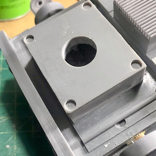
The accompanying photos illustrate where I cut away the damaged portion of the drive section. Once again, I found myself returning to TinkerCad to redesign the intricate pipes and shapes that were removed during this process.
To address the void left in the engine section, I broke out the car body filler. This versatile material proved ideal for smoothing out the area and providing a stable base. Once the filler had set and been appropriately shaped, I carefully affixed my newly printed replacement part into position.
This repair process demonstrates the iterative nature of complex model building, especially when working with 3D printed components. The ability to redesign, reprint, and seamlessly integrate new parts allows for continuous improvement and problem-solving throughout the build.
As I considered the model's substantial weight, I realized the legs alone wouldn't be able to support it. I needed to come up with a plan for a stand and base. The STL documentation included some suggestions from the designer about mounting the finished build, which gave me a starting point.
Typically, I prefer to hide or disguise model stands because I find them distracting. However, given the size of this AT-ST, I knew I'd need a robust stand. There's no way around it - this model requires serious support.
This situation presents an interesting challenge: how to create a stand that's both functional and visually appealing. It's a balance between practical necessity and aesthetic preference.
While I typically love setting my builds in familiar scenes, the sheer size of this AT-ST and the limited display space in my townhome are pushing me to think differently. I need to get creative with my presentation approach.
I've already decided on a solid foundation: a 12x12 piece of plywood will serve as the base. Given these constraints, I'm leaning towards an industrial aesthetic. I'm envisioning something akin to what a Stormtrooper might encounter at an AT-ST dealership - a sleek display showcasing the walker with its manufacturing specifications outlined on a blueprint.
This concept allows me to create an interesting and thematic presentation without requiring the space of a full diorama. It also adds a unique, almost meta perspective to the model, presenting it as a product within its own universe.
Day 4 - 202403.26
To create a sturdy mounting point for the drive section, which was printed hollow, I had to get creative. I decided to use a threaded sleeve, but needed a way to secure it firmly.
I dug through my parts bin and found an old concrete screw anchor that fit perfectly with the 1/4 inch threaded coupler I planned to use. Here's what I did:
1. First, I drilled a hole in the bottom of the drive section, sized to fit the anchor.
2. Then, I prepared a bed of MiliPut epoxy putty.
3. I inserted the anchor into this epoxy bed.
4. Finally, I filled in all the gaps around the anchor with more MiliPut.
This solution provides a solid mounting point that's well-integrated with the model's structure. The concrete anchor, designed to hold weight in tough conditions, gives me confidence that it'll support the model securely.


